- Ball Valves
- Flanged Floating Ball Valve
- Trunnion Mounted Ball Valves
- Threaded Ball Valves
- Welded End Ball Valves
- Gate Valves
- Flanged Gate Valves
- Welded Gate Valves
- Threaded Gate Valves
- Globe Valves
- Flanged Globe Valves
- Weld End Globe Valves
- Threaded Globe Valves
- Check Valves
- Flanged Check Valves
- Welded Ends Check Valves
- Threaded Check Valves
- Y Type Strainers
- Flanged Y Type Strainers
- Threaded Y Type Strainers
- Forged Steel Valves
- Flanged Forged Steel Valves
- Flanged Forged Steel Gate Valve
- Flanged Forged Steel Pressure Seal Gate Valve
- Flanged Forged Steel Globe Valve
- Flanged Forged Steel Pressure Seal Globe Valve
- Flanged Forged Steel Check Valve
- Flanged Forged Steel Pressure Seal Check Valve
- Flanged Forged Steel Y Type Strainer
- Threaded Forged Steel Valves
- Welded Ends Forged Steel Valves
Flanged Forged Steel Gate Valve
Description
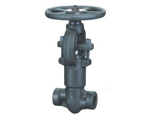
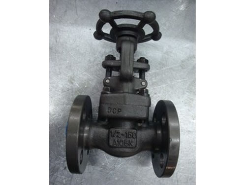
Flanged forged steel gate valve is a kind of most common open/close valve. It is mainly composed of valve body, disc, bonnet, valve gland, gasket, bolt and nut. This flanged gate valve (flanged sluice valve) uses disc to connect or cut off medium in pipeline. Disc functions like a sluice gate to connect or cut off media, so it is called gate valve or sluice valve. The on-off component of gate valve is valve disc. The movement direction of disc is perpendicular to the flowing direction of fluid. Gate valve can only be opened or closed fully.
Applications
Flanged forged steel gate valve can be widely applied as fluid regulating and intercepting equipment in various pipelines, such as tap water, sewage, construction, petroleum, chemical, food, medicine, textile, electric power, shipbuilding, metallurgy, and energy pipeline systems.
Features
1. Sealing material can be selected according to fluid so as to increase sealing property and wear resistance of the flanged gate valve and decrease cost.
2. Flanged sluice valves can be classified according to fluid’s pressure grades (such as 900LB, 1500LB and 2500LB).
3. Flanged forged steel gate valve needs small torsion to open.
4. Valve body adopts precision casting technique.
5. Twice shot blasting processing on outer surface makes the flanged steel valve look fine and smooth.
6. Numerical control processing is utilized on valve disc.
7. Valve seat is replaceable, which makes maintenance more simple and convenient.
Pressure: CLASS900-2500 PN16.0-42.0
1. Welded Bonnet/Pressure Sealed Bonnet
2. Reduced Port
3. Solid Wedge Gate
4. Flange Ends/Butt-Welding Ends
Technical Specification of Flanged Forged Steel Gate Valve
| Technical Specification | ASME/API/BS | GB/JB |
| Design Standard | ASME B16.34/BS5352 | GB/T12235 GB/T12224 |
| Pressure-Temperature Rating | ASME B16.34 | GB/T12224 |
| Face-Face | ASME B16.10 | GB/T12221 JB/T96-95 |
| Flange Ends | ASME B16.5 | GB/T9113JB/T82.1~82.4 |
| Butt Welding Ends | ASME B16.25 | GB/T12224 |
| Inspection & Test | API598 | JB/T9092 |
Material List for Main Parts of Flanged Forged Steel Gate Valve
| No. | Part Name | ASTM | |||
| Carbon Steel | Tailess Steel | Alloy Steel | |||
| 1 | Body | A105 | LF2/LF3 | A182 F304 | A182 F11/F22 |
| 2 | Disc | A182F6a | A182F6a | A182 F304 | A182 F6a |
| 3 | Stem | A276-410 | A276-410 | A276-304 | A276-410 |
| 4 | Gasket | Graphite + 304 | |||
| 5 | Sealing Ring | Graphite | |||
| 6 | Yoke | A216-WCB | A216-WCB | A351 CF8 | A216-WCB |
| 7 | Bonnet | A105 | LF2/LF3 | A182 F304 | A182 F11/F22 |
| 8 | Gland | A216-WCB | A216-WCB | A351 CF8 | A216-WCB |
| 9 | Bolt | A193 B7 | A320L7 | A193 B8 | A193 B16 |
| 10 | Packing | Graphite | |||
| 11 | Stem Bushing | A276-410 | A276-410 | A276-304 | A276-410 |
| 12 | Gland | A216-WCB | A216-WCB | A351 CF8 | A216-WCB |
| 13 | Eye Blot | A193 B7 | A320 L7 | A193 B8 | A193 B7 |
| 14 | Stem Nut | A276-410 | |||
| 15 | Hand Wheel | A197 or A47-32510 | |||
Main Dimensions & Weight
| Pressure | Size | Main Dimension of Valve | Weight(kg) | ||||||||||
| mm | in. | d | LRF | LBW | LRTJ | H | W | ||||||
| WB | PB | WB | PB | ||||||||||
| CLASS900 PN16.0 | 15 | 1/2 | 10 | 216 | 216 | 216 | 197 | 321 | 180 | 9.8 | 11.5 | ||
| 20 | 3/4 | 13 | 229 | 229 | 229 | 211 | 321 | 180 | 9.7 | 11.2 | |||
| 25 | 1 | 19 | 254 | 254 | 254 | 238 | 321 | 180 | 9.5 | 10.8 | |||
| 32 | 1-1/4 | 24 | 279 | 279 | 279 | 257 | 380 | 200 | 17.5 | 18 | |||
| 40 | 1-1/2 | 40 | 305 | 305 | 305 | 276 | 414 | 200 | 21.6 | 22 | |||
| 50 | 2 | 50 | 368 | 368 | 371 | 320 | 502 | 300 | 42.7 | 44 | |||
| CLASS1500 PN26.0 | 15 | 1/2 | 10 | 216 | 216 | 216 | 197 | 321 | 180 | 9.8 | 11.5 | ||
| 20 | 3/4 | 13 | 229 | 229 | 229 | 211 | 321 | 180 | 9.7 | 11.2 | |||
| 25 | 1 | 19 | 254 | 254 | 254 | 238 | 321 | 180 | 9.5 | 10.8 | |||
| 32 | 1-1/4 | 24 | 279 | 279 | 279 | 257 | 380 | 200 | 17.5 | 18 | |||
| 40 | 1-1/2 | 40 | 305 | 305 | 305 | 276 | 414 | 200 | 21.6 | 22 | |||
| 50 | 2 | 50 | 368 | 368 | 371 | 320 | 502 | 300 | 42.7 | 44 | |||
| CLASS2500 PN42.0 | 15 | 1/2 | 10 | 264 | 264 | 264 | 197 | 321 | 180 | 12.3 | 13 | ||
| 20 | 3/4 | 13 | 273 | 273 | 273 | 211 | 321 | 180 | 12.1 | 12.7 | |||
| 25 | 1 | 19 | 308 | 308 | 308 | 238 | 321 | 180 | 11.8 | 12.5 | |||
| 32 | 1-1/4 | 24 | 349 | 349 | 352.2 | 257 | 380 | 200 | 20.9 | 21.8 | |||
| 40 | 1-1/2 | 40 | 384 | 384 | 387.2 | 276 | 414 | 200 | 27.5 | 29.3 | |||
| 50 | 2 | 50 | 451 | 451 | 454.2 | 320 | 502 | 300 | 53.3 | 55.4 | |||
Attentions When Selecting Flanged Forged Steel Gate Valves
1. Medium (Flanged Gate Valve’s Material and Corrosivity)
2. Working Pressure (Intensity and Airtightness)
3. Working Temperature
4. Size of Diameter
5. Valve Form (Category, Structure and Connection Type)
Payment, Package, Delivery and Maintenance
1. Products can be paid by T/T, D/P, D/A, L/C or according to your requirement.
2. Flanged gate valves (flanged sluice valves) are packaged by standard exported wooden cases.
3. Our flanged forged steel gate valves are transported by sea, railway or air.
4. Guarantee period of our products is 18 months. Lifelong technology service is offered.

- Flanged Forged Steel Pressure Seal Gate ValveForged steel flanged pressure seal gate valve is the most common on-off valve. This pressure seal valve is mainly composed of valve body, disc, bonnet, valve gland, gasket, bolt and nut. Disc is the on-off component. It utilizes disc to connect (by fully opened) or cut off (by fully closed) the medium in the pipeline. The disc moves up and down in the direction ...


